The operation of the Whalen system is not just a theory. It’s been operating successfully in thousands of installations worldwide for four decades. Even so, the riser heat-exchanger is still a new concept to many people. What follows is an explanation of how this unique system works. As with any new and unfamiliar idea, there may be questions. A consultation with our engineers is always welcomed.
Innoline® Riser Fan Coil System Basics
In the riser heat-exchanger system, all the water for each tier of units passes through each unit twice. Both the copper supply and return risers are expanded into a single stack of aluminum fins in each Whalen unit. Published capacities are based on the average water temperature for the tier, which is also the average water temperature for each unit in the tier.
Good engineering practices usually dictate that the average chilled water temperature be in the range of 46 degrees F to 50 degrees F.
Energy Savings
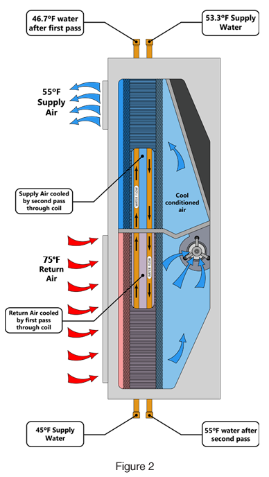
Return air is drawn across the lower half of the Whalen riser heat-exchanger and blown across the upper half – thus duplicating, in effect, a four-row cooling coil. This design, combined with a comparatively large amount of both primary and secondary cooling surface in the finned riser coil, enables the system designer to utilize high delta-T and low GPM/ton where minimum pumping horsepower (and/or smaller piping) is the primary consideration.
Lower System Friction Losses
With conventional horizontal or console fan-coil systems, pump selection is based on the total water friction in the mains, risers, runouts, control valves, and unit coil. Even with other "stacked" fan coil systems, water friction is reduced only by the elimination of the runouts.
In Whalen's Innoline® Riser Fan Coil heat-exchanger system, chilled water friction losses are the total of mains and risers – period. No runouts. No control valves. No separate coil. An attractive savings in pumping horsepower is the result.
There are many successful Whalen installations with a delta-T of 16 degrees F. Obviously, chiller power consumption at various chilled water temperatures and flow rates must be considered in conjunction with selecting the circulating pumps.
Chiller kW/ton savings with higher chilled water temperatures must also be weighed against increased fan horsepower in the larger fan-coil terminal units required with elevated chilled water temperatures.
Variable Speed Pumps
The Whalen rise heat-exchanger system is fully compatible with both variable speed pumps and multiple pumps piped in parallel, so that individual pumps can be shut down under part-load conditions.
Usually, the small reduction in Whalen unit capacity when the riser water flow is reduced is more than offset by the capacity increase that results from reduced average water temperatures at part load (when some units on the riser will normally be turned off or their thermostats will not be calling for cooling). Instead of attempting to force the chilled water pump back up its curve far enough to trip a pressure switch, all that's required with the Whalen system is a return water temperature sensor to control the chilled water pump (similar to most chiller controls).
We recommend that the system designer consider possible energy savings with reduced pump horsepower at part-load conditions within the building envelope.
Water Temperature in Individual Units for Low Rise
As an example of how the individual units in a tier operate, the Figure 1 diagram shows a typical tier of Whalen units. In this 3-story building, the designer has decided to upfeed three floors from mains in the basement. (Alternatively, the designer could also downfeed the units from mains located in the third floor ceiling.)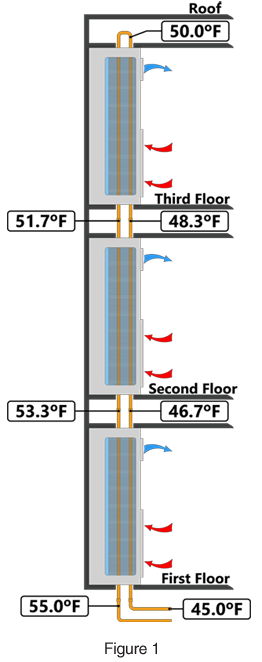
- Chilled water enters the riser heat-exchanger of the first floor Whalen unit at 45 degrees F and absorbs heat from the room. In this example, the temperature rise of the water is 1.7 degrees F in each pass through a single unit, so the water will enter the second floor unit at 46.7 degrees F.
- Assuming that all unit thermostats are calling for cooling, the temperature of the water in the supply riser will increase at a rate of 1.7 degrees F per floor, with the entering water temperature of the second floor unit being about 48.3 degrees F.
- The water loops around a factory-installed top U-bend (with air vent) and begins its descent through the return riser, leaving the third floor at 51.7 degrees F. In the top floor unit, as in all other units in the tier, the air passing over the riser heat-exchanger coil is cooled by an average water temperature of 50.0 degrees F.
- If some thermostats in the tier of units are satisfied, those units will not warm the water passing through them. This results in a reduction in average water temperature in the whole tier of units, with an accompanying increase in cooling capacity in those units with thermostats calling for cooling. (See Figure 2)
- The average of the water temperatures in any unit is a constant 50.0 degrees F in this example. Of course, the designer could make use of a different entering water temperature and design for a different temperature rise through each unit. The overall result would be the same: The average water temperature in each separate unit is the same as the average temperature of the water entering and leaving the tier.
| Note: Extensive testing at various temperatures and flow rates confirms that all units in this example have nearly identical sensible and total cooling capacities regardless of their position in the tier. The average water temperature concept is independent of the number of units in the tier. In the example shown, the average water temperature would be 50.0 degrees F whether the building is two stories tall, 82 stories tall – or anything in between. |
Water Temperature in Individual Units for High Rise
As an example of how the individual units in a tier operate, please refer to the adjacent diagram (Figure 3) showing a typical tier of Whalen units. In this 35-story building, the designer has decided to upfeed 35 floors from mains in the basement. (Alternatively, the designer could also downfeed the units from mains located in the 35th floor ceiling.)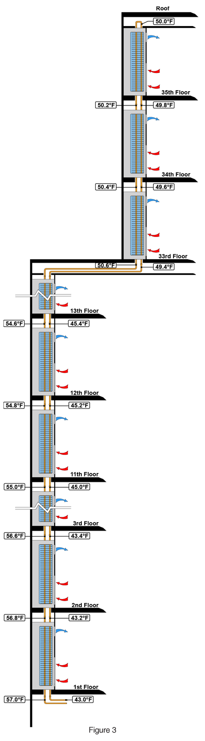
- Chilled water enters the riser heat-exchanger of the first floor Whalen unit at 43 degrees F and absorbs heat from the room. In this example, the temperature rise of the water is 0.2 degrees F in each pass through a single unit, so the water will enter the second floor unit at 43.2 degrees F.
- Assuming that all unit thermostats are calling for cooling, the temperature of the water in the supply riser will increase at the rate of 0.2 degrees F per floor, with the entering water temperature of the 35th floor unit being 49.8 degrees F.
- The water loops around a factory-installed top U-bend (with air vent) and begins its descent through the return riser, leaving the 35th floor at 50.2 degrees F. In the top floor unit, as in all other units in the tier, the air passing over the riser heat-exchanger coil is cooled by an average water temperature of 50.0 degrees F.
- If some thermostats in the tier of units are satisfied, those units will not warm the water passing through them. This results in a reduction in average water temperature in the whole tier of units, with an accompanying increase in cooling capacity in those units with thermostats calling for cooling.
- The average of the water temperatures in any unit is a constant 50.0 degrees F in this example. Of course, the designer could make use of a different entering water temperature and design for a different temperature rise through each unit. The overall result would be the same: The average water temperature in each separate unit is the same as the average temperature of the water entering and leaving the tier.
| Note: Extensive testing at various temperatures and flow rates confirms that all units in this example have nearly identical sensible and total cooling capacities regardless of their position in the tier. The average water temperature concept is independent of the number of units in the tier. In the example shown, the average water temperature would be 50.0 degrees F whether the building is two stories tall, 82 stories tall – or anything in between. |
Humidity Control
It is well-understood in the engineering profession that face and bypass control of cooling is superior to valve control. Many valve-control fan-coil unit installations, unlike Whalen face and bypass damper installations, are described by laymen as having conditioned spaces that are "cold and clammy."
Whalen face and bypass damper control units do not re-evaporate condensate from the cooling coil and put it back into the conditioned space when the thermostat is satisfied. Instead, Whalen electric heat 2-pipe and 4-pipe units are furnished with face and bypass damper control of cooling. The 2-pipe changeover units are available with a face and bypass damper control as an available option.